Intro
Simply said: Input Shaping or Resonance Compensation is a technic to reduce vibrations and resonances by proactive adjusting the printer movements. It increases the max possible printer speed without reducing the print quality. More details can be found in Klipper Resonance Compensation documentation.
This article focuses on Klipper firmware, but also Marlin added Input Shaping as experimental feature in its latest Version. see M593.
There is also a manual way to determine the resonance frequencies but this post shows you the steps to measure the frequencies by an ADXL345 accelerometer chip. You can get it for some bucks.
Ready? Let’s start!
Requirements
What do you need?
- Your printer (tested with Artillery Sidewinder X2)
- A working Klipper installation (tested with MainsailOS)
- Jumper cables or similar
- ADXL345 accelerometer module
- Adapter to mount it on your extruder see my Design
- Raspberry Pi (or any other connected MCU with SPI interface)
Install and wire the accelerometer
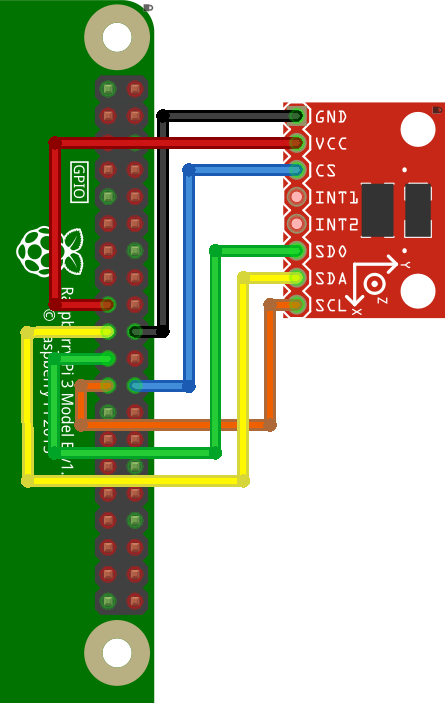
As always, Klipper has a very clean and useful documentation. It describes well how to wire the accelerometer.
A example how to connect your ADXL345 to the SPI interface of the RaspberryPI. Here is a copy of the relevant wiring diagram:

I used standard jumper cables for that task, but in case you want to do some crafting, go on.
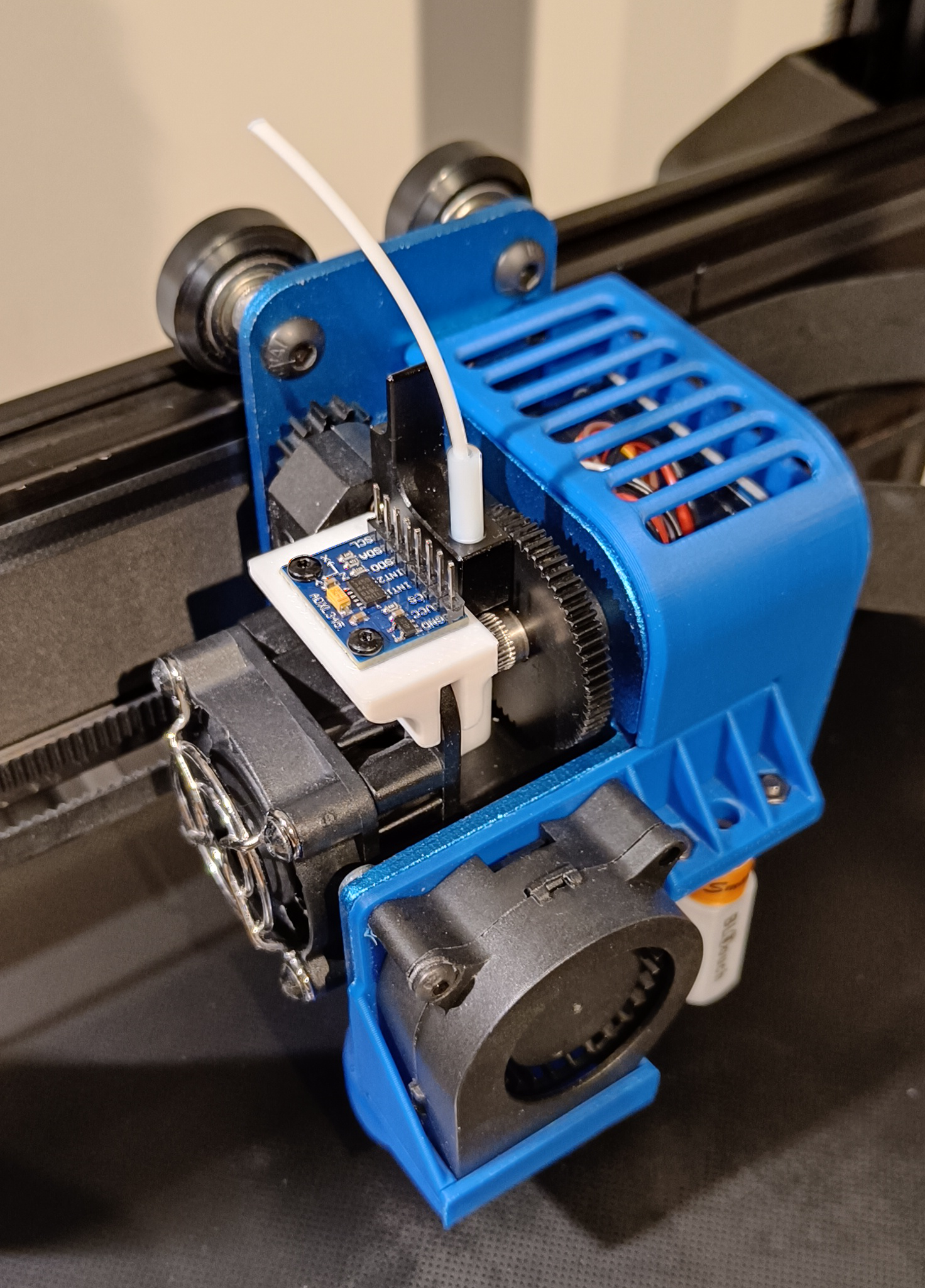
If you have the Sidewinder X1/X2 or Genius Pro you can use my mount from Thingiverse to install the accelerometer on your extruder. I suggest V2, the sensor is in parallel to the xy-plane and mounted with screws. Because those are bed slingers, the measurement of the resonance frequency should be split. For measure the frequency for y-axis, you should install the accelerometer on your heater bed. I made an adapter for that too. (Thanks to Paradisebaker to clarify that.)
If you own another printer, you have to look for different mounting solution.

Build a Klipper MCU for PI
To make use of the SPI interface, you need to build and setup a additional Klipper firmware for your target. So you can configure it as an MCU in your config files.
Software installation
Detailed Klipper documentation
Login to your MainsailOS PI
Make sure, needed packages are installed. (In newer MainsailOS everything is already installed)
sudo apt update
sudo apt install python3-numpy python3-matplotlib libatlas-base-dev
~/klippy-env/bin/pip install -v numpy
Build secondary MCU for PI
RPi Micro-Controller documentation
First, make sure the Linux SPI driver is enabled by running
sudo raspi-configand enabling SPI under the “Interfacing options” menu.Next, compile the Klipper micro-controller code, start by configuring it for the “Linux process”:
cd ~/klipper/
make menuconfig
In the menu, set “Microcontroller Architecture” to “Linux process,” then save and exit.
Build and install the new micro-controller code, run:
sudo service klipper stop
make flash
sudo service klipper start
Copy a the matching klipper-mcu service, enable and start it.
cd ~/klipper/
sudo cp ./scripts/klipper-mcu.service /etc/systemd/system/
sudo systemctl enable --now klipper-mcu.service
Configure the new compiled RPi MCU in your
printer.cfg[mcu rpi] serial: /tmp/klipper_host_mcu [adxl345] cs_pin: rpi:None axes_map: -y, x, z # Depends on mounting direction. Works for my V2 Mount [resonance_tester] accel_chip: adxl345 probe_points: 150, 150, 20 # mid of your bed (Sidewinder size: 300x300mm)
Test and Calibration steps
Open your G-Code console (for example in Mainsail)
Check if the accelerometer respond. If not, double check the steps above and Klipper documentation.
ACCELEROMETER_QUERYA output should look similar to this
accelerometer values (x, y, z): 536.266849, -888.247130, 9918.759623Check if sensor and wires don’t have to much noise
MEASURE_AXES_NOISEAll values should be below 100
Axes noise for xy-axis accelerometer: 11.789601 (x), 16.017559 (y), 29.190110 (z)
If you have problems, consult Checking the setup
Manual Test X- and Y-Axes
Test x-axis resonances on G-Code console (for example in Mainsail). Mount your ADXL345 on your extruder
TEST_RESONANCES AXIS=XLogin to your Raspberry Pi terminal (with ssh)
Run the
calibrate_shaper.pywith the generated csv, also generate a beautiful diagram over the measured and calculated frequencies.Example:
~/klipper/scripts/calibrate_shaper.py /tmp/resonances_x_*.csv -o ~/printer_data/config/shaper_calibrate_x.png

Fitted shaper 'zv' frequency = 53.8 Hz (vibrations = 11.0%, smoothing ~= 0.060)
To avoid too much smoothing with 'zv', suggested max_accel <= 11300 mm/sec^2
Fitted shaper 'mzv' frequency = 55.0 Hz (vibrations = 0.0%, smoothing ~= 0.067)
To avoid too much smoothing with 'mzv', suggested max_accel <= 8900 mm/sec^2
Fitted shaper 'ei' frequency = 69.4 Hz (vibrations = 1.4%, smoothing ~= 0.067)
To avoid too much smoothing with 'ei', suggested max_accel <= 9000 mm/sec^2
Fitted shaper '2hump_ei' frequency = 81.8 Hz (vibrations = 0.0%, smoothing ~= 0.081)
To avoid too much smoothing with '2hump_ei', suggested max_accel <= 7400 mm/sec^2
Fitted shaper '3hump_ei' frequency = 98.4 Hz (vibrations = 0.0%, smoothing ~= 0.085)
To avoid too much smoothing with '3hump_ei', suggested max_accel <= 7100 mm/sec^2
Recommended shaper is mzv @ 55.0 Hz
Test y-axis resonances on G-Code console (for example in Mainsail). Mount your ADXL345 on your heat bed. There is also an adapter on my thingiverse page
TEST_RESONANCES AXIS=YLogin to your Raspberry Pi terminal (with ssh)
Run the
calibrate_shaper.pywith the generated csv, also generate a beautiful diagram over the measured and calculated frequencies.Example:
~/klipper/scripts/calibrate_shaper.py /tmp/resonances_y_*.csv -o ~/printer_data/config/shaper_calibrate_y.png

Fitted shaper 'zv' frequency = 39.6 Hz (vibrations = 18.1%, smoothing ~= 0.102)
To avoid too much smoothing with 'zv', suggested max_accel <= 6100 mm/sec^2
Fitted shaper 'mzv' frequency = 30.8 Hz (vibrations = 1.0%, smoothing ~= 0.215)
To avoid too much smoothing with 'mzv', suggested max_accel <= 2800 mm/sec^2
Fitted shaper 'ei' frequency = 41.6 Hz (vibrations = 1.3%, smoothing ~= 0.186)
To avoid too much smoothing with 'ei', suggested max_accel <= 3200 mm/sec^2
Fitted shaper '2hump_ei' frequency = 40.2 Hz (vibrations = 0.0%, smoothing ~= 0.334)
To avoid too much smoothing with '2hump_ei', suggested max_accel <= 1700 mm/sec^2
Fitted shaper '3hump_ei' frequency = 48.0 Hz (vibrations = 0.5%, smoothing ~= 0.356)
To avoid too much smoothing with '3hump_ei', suggested max_accel <= 1500 mm/sec^2
Recommended shaper is ei @ 41.6 Hz
Configure input_shaper section in
printer.cfg. You can take the following snipped and replace your calculated and chosen frequencies and algorithm.Example:
[input_shaper]
shaper_freq_x: 55.0
shaper_type_x: mzv
shaper_freq_y: 41.6
shaper_type_y: ei
Alternative auto calibrate
If you are not interested in any details, you can use the automatic SHAPER_CALIBRATE script. See Input Shaper auto-calibration documentation.
In short:
SHAPER_CALIBRATEor
SHAPER_CALIBRATE AXIS=X or SHAPER_CALIBRATE AXIS=YDon’t forget to save your config
SAVE_CONFIG
Conclusion
Hope this was straight forward and you could successful measure your resonances. Now you should be able to print faster with your Artillery Sidewinder X2. Try to increase your acceleration and speed.
For further steps and more details it is always a very good idea to walk through the very good official documentations
Please leave a comment if there is something wrong or missing. Or if you have any questions. Have fun!
If you enjoyed this article and would like to support my work, feel free to buy me a coffee! Your support helps me continue creating content. Thank you!
